The Fail Safe Tester (FST) is the ideal component to simulate electrical faults, such as cable breaks, short circuits or loss of contact in a controlled and reproducible way, and to manipulate signal paths. The goal is to be able to observe the behavior of the device under test. The Fail Safe Tester enables different types and combinations of signal lines between the control unit and the peripheral. For this purpose, it is inserted between the HIL system and the ECU under test, or between multiple ECUs.
Up to 160 channels per Fail Safe Tester are available. To further increase the number of channels, more than one device can be cascaded if necessary. The Fail Safe Tester can be used as a standalone device controlled via a CAN or a serial interface. Another option is to combine it with the simulation software CarMaker or the RealtimeMaker by IPG Automotive. Both provide the Fail Safe Tester with a graphic user interface. This makes it an ideal complement for the turnkey test systems. The modular and compact structure in a 19’’ housing allows for easy integration into test designs.
The Fail Safe Tester can imitate the following possible faults:
- Interrupted signal lines (cable breaks)
- Mixed up signal lines
- Short circuits (with other electric lines)
- Increased contact resistance (for example because of corrosion)
- Leakage current (for example due to humidity)
- Loss of contact (loose contact)
The basic functionality is provided primarily by relay switching. In addition, six “Interconnection Lines” are available inside the Fail Safe Tester. They connect the respective plug-in cards. Every signal line can be connected to the internal connection lines via relay contacts. Signals of different cards can therefore be interconnected.
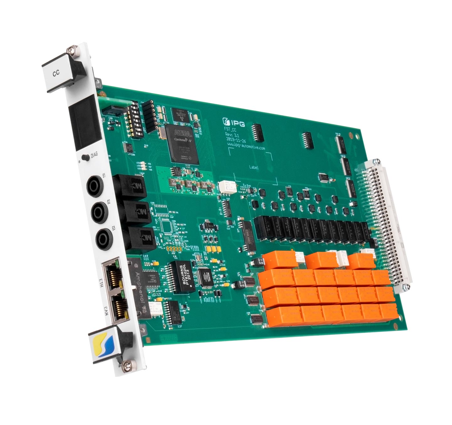
The controller card is an integral part of the system. It receives control commands, controls the connections of the internal connection lines, enables measurement via banana jacks and allows for self-diagnosis of the entire system. Furthermore, a variety of modular plug-in cards is available (Standard Relay Card, High Current Relay Card, High Voltage Card and Programmable Resistor Card).
Your benefits at a glance
User-friendliness
Complete configuration via software, no need to plug in cables manually
Reusability
Easily save and reproduce the entire test configuration
Test automation
Full automation of tests
High capacity
Up to 160 channels in a compact housing
Scalability
Expandable by cascading multiple devices
Modular design
Easy connection and extension
Modular plug-in cards
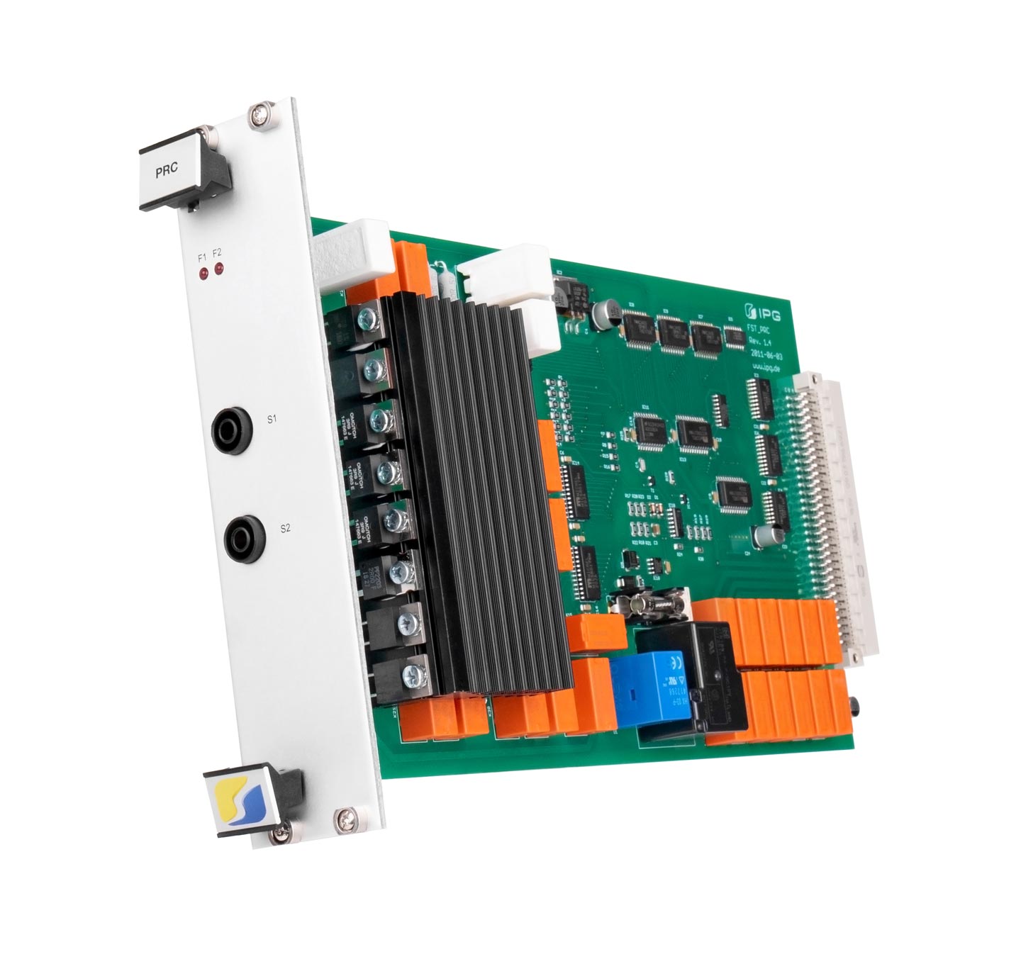
Functions:
- Control of the overall system by executing commands received via CAN or serial interface RS232/COM
- Control of the connections of the interconnection lines 1 and 4, 2 and 5, 3 and 6
- Measurement of up to 3 signals (S1 .. S3)
- Self-diagnosis, digital DIAG to test relay, analog DIAG to test resistance values
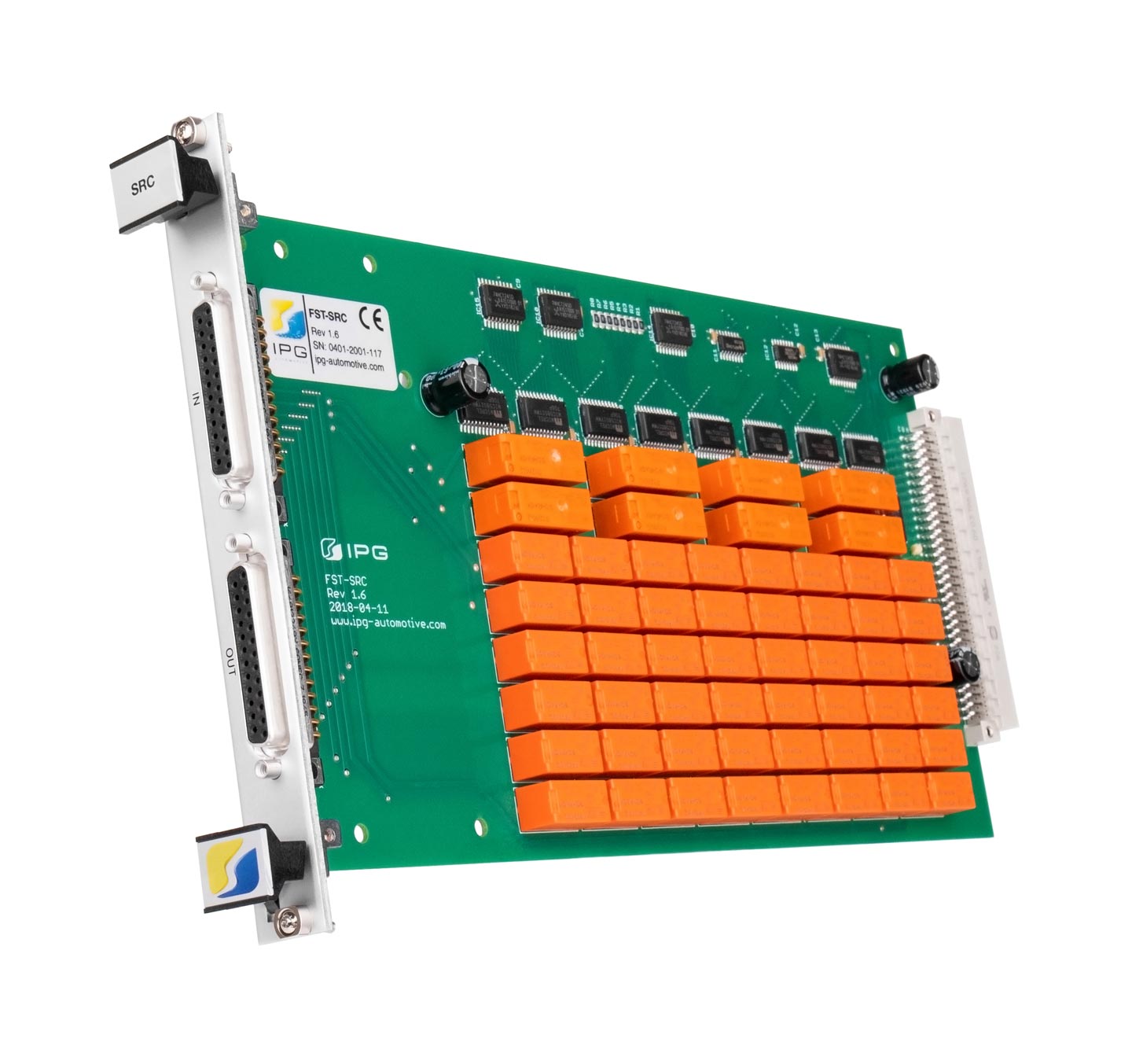
Functions:
Every channel of the Standard Relay Card is equipped to
- connect/disconnect the input and output of a channel.
- interconnect multiple inputs and outputs located on the same card or on different cards.
- connect any input to any output located on the same card or on different cards
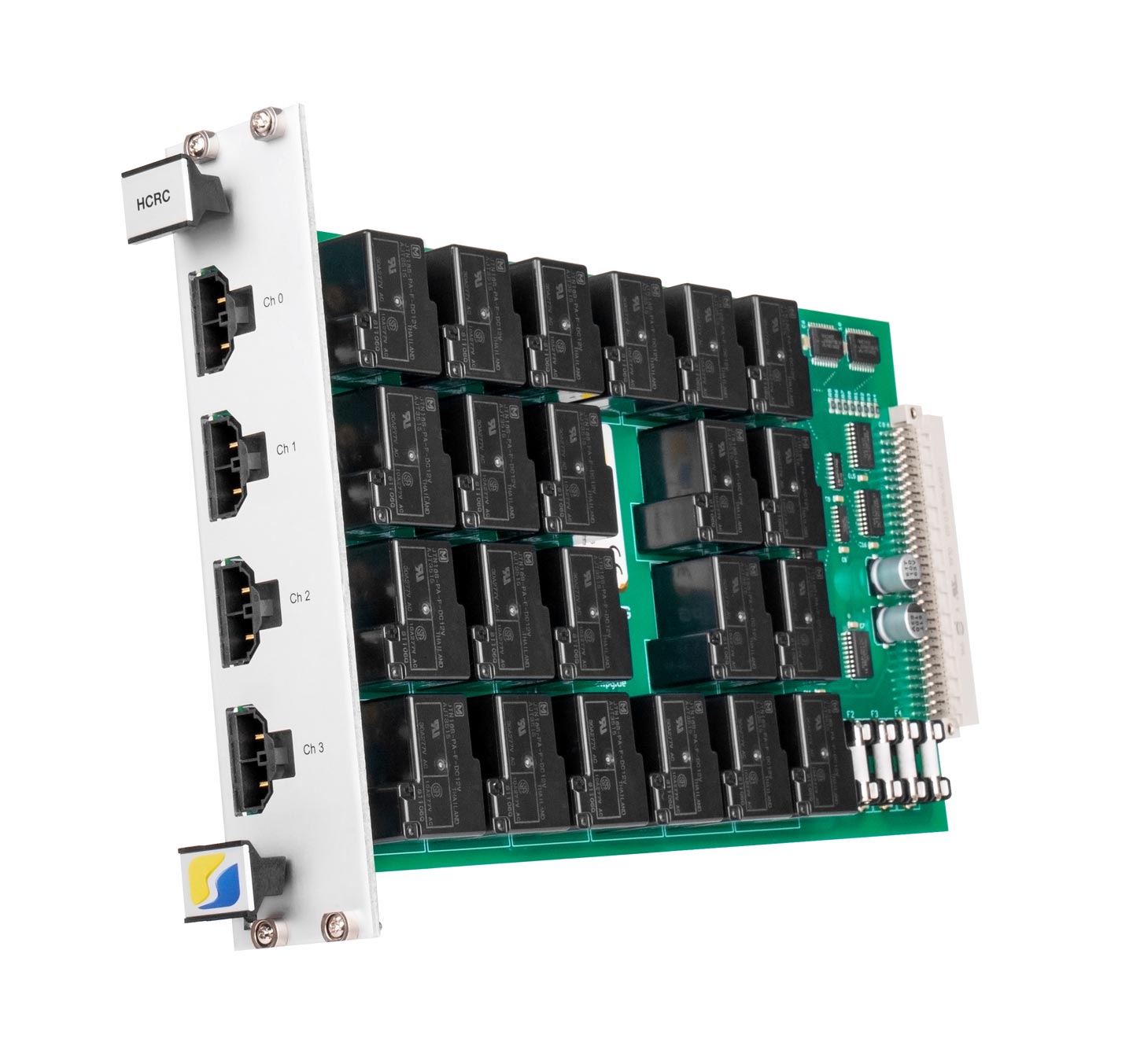
Functions:
Every channel of the High Current Relay Card is equipped to
- connect/disconnect the input and output of a channel.
- interconnect multiple inputs and outputs located on the same card or on different cards.
- connect any input to any output located on the same card or on different cards.
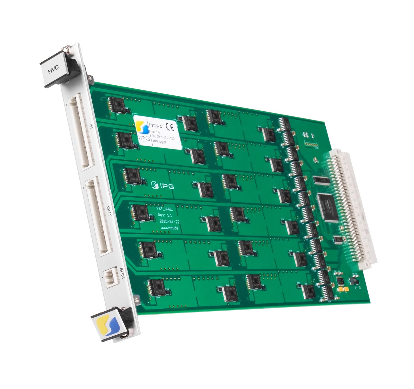
Functions:
Every channel of the High Voltage Card is equipped to
- connect/disconnect the input and output of a channel.
- connect multiple inputs and outputs located on the same card.
- connect every output with the „SUM“ point.
Functions:
The Programmable Resistor Card is equipped to
- insert any resistance between the input and the output of a channel.
- insert any resistance between different signal lines of a channel.
- connect external loads via the banana jacks.